- 您现在的位置:买卖IC网 > Sheet目录346 > NCP5623CMUTBG (ON Semiconductor)IC LED DRIVER RGB I2C 12-LLGA
NCP5623C
B7
B6
B5
B4
B3
B2
B1
B0
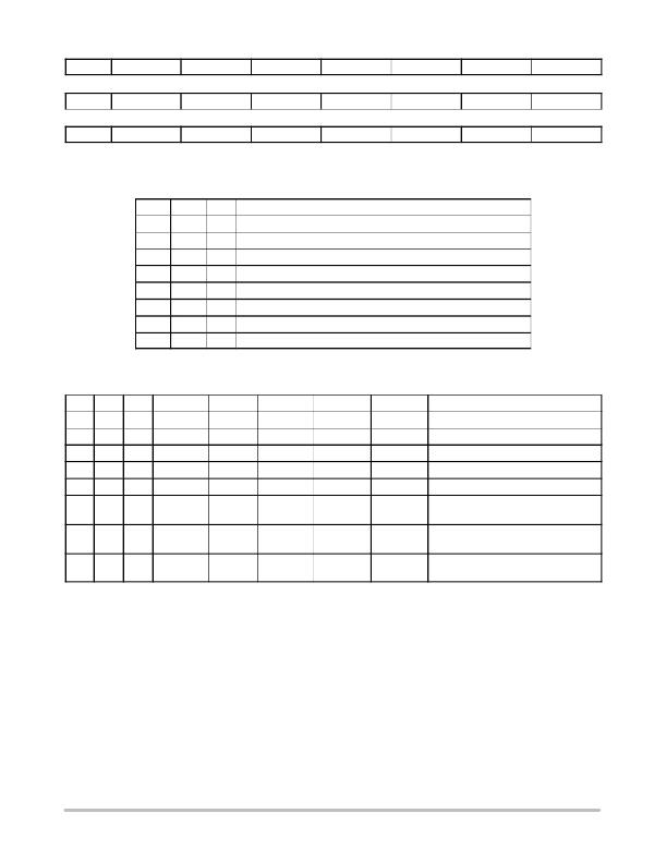
Byte#1 : I 2 C Physical Address, based 7 bits : % 011 1001 3 $39 *
0
1
1
1
0
0
1
R/W
Byte#2 : DATA register
RLED2
RLED1
RLED0
BLED4
BLED3
BLED2
BLED1
BLED0
*Note: according to the I 2 C specifications, the physical address is based on 7 bits out of the SDA byte, the 8 th bit representing the R/W command.
Since the NCP5623C is a receiver only, the R/W command is 0 and the hexadecimal byte send by the MCU is %0111 0010 = $72
B[7:5] : Internal Register Selection:
B7
0
0
0
0
1
1
1
1
B6
0
0
1
1
0
0
1
1
B5
0
1
0
1
0
1
0
1
Function
Chip Shut Down 3 all LED current = zero
Set up the maximum Output LED Current
PWM1 : LED1 control
PWM2 : LED2 control
PWM3 : LED3 control
Set the Upward Iend target
Set the Downward Iend target
Set the number of steps and activate the Gradual Dimming
The contain of bits B[4:0] depends upon the type of function selected by bits B[7:5] as depicted in Table 1
Table 1. Internal Register Bits Assigmen t
B7
0
0
0
0
1
1
B6
0
0
1
1
0
0
B5
0
1
0
1
0
1
B4
X
16
BPWM16
BPWM16
BPWM16
GDIM5
B3
X
8
BPWM8
BPWM8
BPWM8
GDIM4
B2
X
4
BPWM4
BPWM4
BPWM4
GDIM3
B1
X
2
BPWM2
BPWM2
BPWM2
GDIM2
B0
X
1
BPWM1
BPWM1
BPWM1
GDIM1
Comments
Shut down
Output LED Step, see Figure 4 (Note 11)
PWM1
PWM2
PWM3
Set Gradual Dimming
16
8
4
2
1
Upward Iend Target (Note 12)
1
1
0
GDIM5
GDIM4
GDIM3
GDIM2
GDIM1
Set Gradual Dimming
16
8
4
2
1
Downward Iend Target (Note 12)
1
1
1
GDIM5
GDIM4
GDIM3
GDIM2
GDIM1
Gradual Dimming
128 ms
64 ms
32 ms
16 ms
8 ms
Step Number & run
11. The programmed current applies to the three LED simultaneously, the gradual dimming is not engaged
12. The bit values represent the steps count, not the ILED current: see equations 1 & 2, page 7, to derive the ILED value.
GRADUAL DIMMING
The purpose of that function is to gradually Increase or
Decrease the brightness of the backlight LED upon
command from the external MCU. The function is activated
and controlled by means of the I 2 C protocol.
In order to avoid arithmetic division functions at silicon
level, the period (either upward or downward) is equal to the
time defined for each step, multiplied by the number of
steps.
To operate such a function, the MCU will provide three
information:
1 – The target current level (either upward or downward)
2 – The time per step
3 – The Upward or Downward mode of operation
When a new gradual dimming sequence is requested, the
output current increases, according to an exponential curve,
from the existing start value to the end value. The end current
value is defined by the contain of the Upward or Downward
registers, the width of each step is defined by the third
register, the number of step being in the 1 to 30 range. In the
event of software error, the system checks that neither the
maximum output current (30 mA), nor the zero level are
forced out of their respective bounds. Similarly, software
errors shall not force the NCP5623C into an uncontrolled
mode of operation.
http://onsemi.com
8
发布紧急采购,3分钟左右您将得到回复。
相关PDF资料
NCP5680MUTXG
IC LED DRIVER WHT HI EFF 24-UQFN
NCP5890MUTXG
IC LED DRVR WHITE BCKLGT 16-UQFN
NCP5901BMNTBG
IC MOSFET DVR SYNC VR12 8-DFN
NCP5901MNTBG
IC MOSFET DVR SYNC VR12 8-DFN
NCP5911MNTBG
IC MOSFET DVR SYNC VR12 8-DFN
NCP692MN50T2GEVB
EVAL BOARD FOR NCP692MN50T2G
NCV7513AFTR2G
IC PREDRIVER HEX LOW SIDE 32LQFP
NCV7513BFTR2G
IC PREDRIVER HEX LOW SIDE 32LQFP
相关代理商/技术参数
NCP5623DTBR2G
功能描述:LED照明驱动器 RGB LED DRIVER W/I2C RoHS:否 制造商:STMicroelectronics 输入电压:11.5 V to 23 V 工作频率: 最大电源电流:1.7 mA 输出电流: 最大工作温度: 安装风格:SMD/SMT 封装 / 箱体:SO-16N
NCP5623MUTBG
功能描述:IC LED DRIVER RGB 12-LLGA RoHS:是 类别:集成电路 (IC) >> PMIC - LED 驱动器 系列:- 标准包装:1 系列:- 恒定电流:- 恒定电压:- 拓扑:PWM,切换式电容器(充电泵) 输出数:1 内部驱动器:是 类型 - 主要:背光 类型 - 次要:白色 LED 频率:642kHz 电源电压:2.7 V ~ 5.5 V 输出电压:5V 安装类型:表面贴装 封装/外壳:10-VFDFN 裸露焊盘 供应商设备封装:10-VSON 包装:剪切带 (CT) 工作温度:-30°C ~ 85°C 产品目录页面:1371 (CN2011-ZH PDF) 其它名称:BD1603NUV-E2CT
NCP562-SKT
制造商:ON Semiconductor 功能描述:80 mA CMOS Low Iq Low-Dropout Voltage Regulator 制造商:P&S 功能描述:80 mA CMOS Low Iq Low-Dropout Voltage Regulator
NCP562SQ15T1
功能描述:低压差稳压器 - LDO 1.5V 80mA CMOS RoHS:否 制造商:Texas Instruments 最大输入电压:36 V 输出电压:1.4 V to 20.5 V 回动电压(最大值):307 mV 输出电流:1 A 负载调节:0.3 % 输出端数量: 输出类型:Fixed 最大工作温度:+ 125 C 安装风格:SMD/SMT 封装 / 箱体:VQFN-20
NCP562SQ15T1G
功能描述:低压差稳压器 - LDO 1.5V 80mA CMOS w/Enable RoHS:否 制造商:Texas Instruments 最大输入电压:36 V 输出电压:1.4 V to 20.5 V 回动电压(最大值):307 mV 输出电流:1 A 负载调节:0.3 % 输出端数量: 输出类型:Fixed 最大工作温度:+ 125 C 安装风格:SMD/SMT 封装 / 箱体:VQFN-20
NCP562SQ18T1
功能描述:低压差稳压器 - LDO 1.8V 80mA CMOS RoHS:否 制造商:Texas Instruments 最大输入电压:36 V 输出电压:1.4 V to 20.5 V 回动电压(最大值):307 mV 输出电流:1 A 负载调节:0.3 % 输出端数量: 输出类型:Fixed 最大工作温度:+ 125 C 安装风格:SMD/SMT 封装 / 箱体:VQFN-20
NCP562SQ18T1G
功能描述:低压差稳压器 - LDO 1.8V 80mA CMOS w/Enable RoHS:否 制造商:Texas Instruments 最大输入电压:36 V 输出电压:1.4 V to 20.5 V 回动电压(最大值):307 mV 输出电流:1 A 负载调节:0.3 % 输出端数量: 输出类型:Fixed 最大工作温度:+ 125 C 安装风格:SMD/SMT 封装 / 箱体:VQFN-20
NCP562SQ21T1G
功能描述:低压差稳压器 - LDO 80MA 2.1V LDO W/ ENABLE RoHS:否 制造商:Texas Instruments 最大输入电压:36 V 输出电压:1.4 V to 20.5 V 回动电压(最大值):307 mV 输出电流:1 A 负载调节:0.3 % 输出端数量: 输出类型:Fixed 最大工作温度:+ 125 C 安装风格:SMD/SMT 封装 / 箱体:VQFN-20
